History technology of induction melting furnace :
In the traditional coreless induction melting furnace structure, the magnetic flux of the intermediate frequency induction coil follows the melting zone in the furnace and the external magnetic circuit of the induction coil.
And the outer shell of the electric furnace is closed, and the outer circle, the bottom and the upper cover part of the furnace shell are induced by the alternating magnetic flux passing through.
Flow, a large-capacity steel shell induction melting furnace is provided with an outer yoke of an induction coil formed by stacking silicon steel sheets. The manufacturing process of the yoke is complicated, and a magnetic flux of several hundred hertz is also generated on the core yoke. Eddy current, due to the eddy current and hysteresis loss of the silicon steel sheet yoke, the no-load loss of the electric furnace is large. The yoke itself also needs water cooling. electric load loss is relatively large, how to further reduce electric load loss and improve energy efficiency, is the need to address a major problem. The low no-load loss induction melting furnace includes a furnace shell, a melting chamber furnace lining and an induction coil, the induction coil is placed between the melting chamber furnace lining and the furnace shell, and a magnetic conductive column and a magnetic conductive column are arranged outside the induction coil. The upper and lower ends of the furnace are respectively connected to the furnace magnetically permeable shielding plate and the furnace bottom magnetically permeable shielding plate. The magnetically conductive pillar and the magnetically shielded plate can be made into appropriate block parts. The magnetically conductive pillar is fixedly surrounded between the outer circle of the induction coil and the furnace shell to form an external magnetic shield circuit of the induction coil. Shielding of the magnetically permeable shield plate at the bottom of the furnace, avoiding and shielding the magnetic flux outside the induction coil from inducing heat through the furnace shell, the bottom of the furnace shell and the cover of the furnace mouth, greatly reducing electricity
No-load loss of the furnace.
The cross-section design of the magnetically conductive column is fan-shaped, and its inner side corresponds to the shape of the induction coil, which can be installed close to the induction coil. The magnetically permeable shielding plate of the furnace mouth can be ring-shaped, it can be a whole ring, or it can be assembled ring. Its 孑L diameter is compatible with the furnace mouth, and the structure is simple and compact. Furnace magnetically permeable shielding plate can be made as an independent part, or it can be directly compounded on the supporting furnace cover. It has good integrity, high overall strength and good performance.
The furnace bottom magnetically permeable shielding plate may be a circular plate, a square plate or a polygonal plate, etc., including integral pieces and assembled pieces, etc., as appropriate. The magnetically conductive columns and magnetically shielded plates are made by sintering, bonding and pressing soft magnetic ferrites or magnetically conductive powders or high-resistance soft magnetic materials with high magnetic permeability and low loss in high-frequency magnetic fields. Compared with silicon steel sheets, the manufacturing process is simple, and the magnetically conductive posts and magnetically shielded plates made of soft ferrite, magnetically conductive powder or high-resistance soft magnetic material have very little eddy current and hysteresis loss, which can make the No-load loss is significantly reduced.
The other structures, power sources and control parts of the induction melting furnace are mature technologies, which can be directly borrowed. This is not the improvement and will not be described again.
A magnetically conductive column is provided between the furnace shell and the induction coil, and a corresponding magnetically conductive shield is provided at the furnace bottom and the furnace mouth
In this way, there is very little alternating magnetic flux passing through the furnace shell, so that the no-load loss of the electric furnace is significantly reduced, and the magnetically conductive posts and guides made of soft ferrite, magnetically conductive powder or high-resistance soft magnetic material The eddy current and hysteresis loss of the magnetic shielding plate are small, which can further reduce the no-load loss of the electric furnace, and improve the electric energy utilization rate and the electric furnace efficiency.
BRIEF DESCRIPTION OF THE DRAWINGS

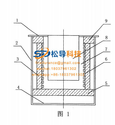
FIG. 1 is a schematic structural diagram of an embodiment.

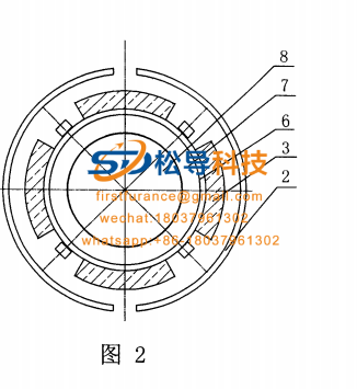
Figure 2 and Figure 1 are schematic diagrams of the AA cross-section structure.

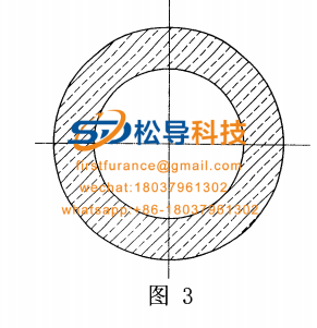
Fig. 3 Schematic diagram of the furnace mouth magnetically conductive shielding plate.

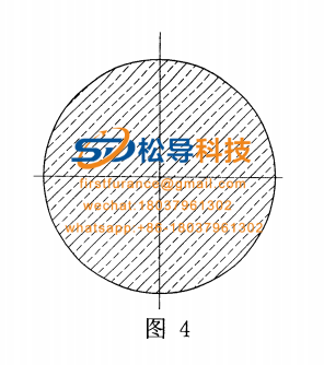
Figure 4 Schematic diagram of the structure of the furnace bottom magnetically permeable shield.
In the picture: 1. Furnace mouth shell 2 , Furnace shell 3 , Magnetically conductive column 4 , Furnace bottom shell 5 , Furnace magnetically shielded plate 6 , Induction coil 7 , Furnace lining 8 , Melting chamber 9 , Furnace magnetically shielded plate,
Specific transformation methods
As shown in the figure, the low no-load loss induction melting furnace includes a furnace shell and a furnace lining 7
And induction coil 6 , the induction coil 6 is placed between the melting chamber furnace lining 7 and the furnace shell 2. The outer side of the induction coil 6 is equipped with a magnetically conductive pillar 3 , and the upper and lower ends of the magnetically conductive pillar 3 are respectively connected to the furnace magnetically shielded plate 9 and the furnace bottom magnetically conductive shielding plate 5 , the cross-section of the magnetically conductive pillar 3 is fan-shaped, and the inside thereof corresponds to the shape of the induction coil 6 . The furnace magnetically conductive shielding plate 9 has a ring shape, and its aperture is suitable for the furnace mouth. The furnace magnetically conductive shielding plate 5 is a circular plate, and the magnetically conductive columns 3 and the magnetically shielding plates 9 and 5 are mainly made of soft ferrite. Raw materials are sintered, bonded and pressed. The magnetically conductive pillars 3 and the magnetically shielded plates 9 and 5 can also be directly sintered, bonded and pressed by using the magnetically conductive powder or the high-resistance soft magnetic material as the main raw material.
http://www.songdaokeji.com/plus/list.php?tid=49
http://www.songdaokeji.com/plus/list.php?tid=22
http://www.songdaokeji.com/plus/view.php?aid=667

