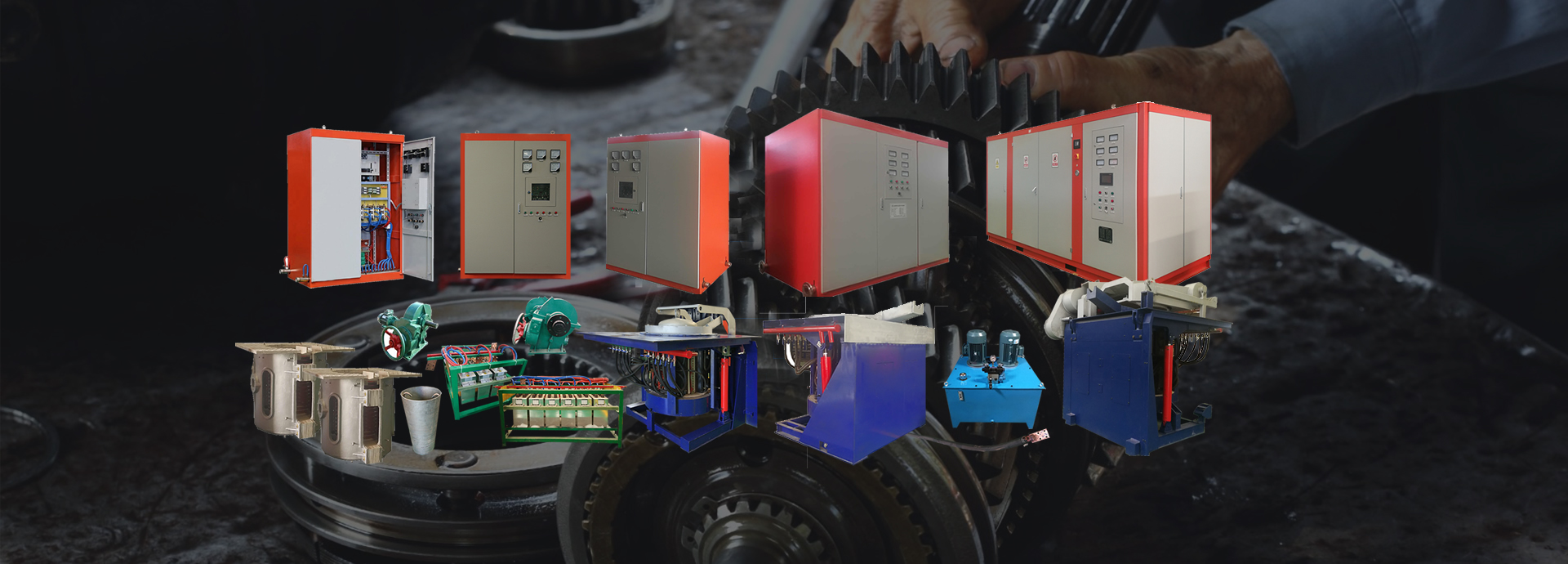
The series intermediate frequency furnace is determined by five major circuits
The series connection of the induction coil of the IF furnace inverter load line and the compensation capacitor is a series IF furnace. The series resonance is also a voltage resonance. The voltage across the induction coil is high. Therefore, the series IF furnace has a better energy saving effect under the same power condition.
The thyristor intermediate frequency power supply forms a series rectifier circuit, the reactor, the capacitor and the choke coil form a filter circuit, and the transistor and the diode form a half-bridge inverter circuit. The input voltage of the three-phase power grid is rectified by a rectifier circuit to form a pulsating DC. Then the reactor smooths the wave and the choke coil blocks the AC current to form a smooth DC. The DC current is filtered and charged to form a stable voltage. The half-bridge inverter circuit inverts the voltage to intermediate frequency voltage and current and sends it to the induction coil.
The main circuit of the series intermediate frequency furnace consists of five links:
① Rectification link (AC-DC), in the rectifier circuit, through the three-phase bridge full-control rectifier circuit, the AC frequency of 50Hz can be rectified into pulsating DC power, and the DC voltage U of the circuit can be changed to change the load current; The load of the intermediate frequency power rectifier circuit is an inverter, and the active power output by the inverter is provided by the rectifier circuit. It is required that the DC output voltage of the rectifier circuit can be continuously smooth and adjustable;
② Filter link (FILTER). In the filter circuit, the power frequency and the intermediate frequency network are separated by Ld, and at the same time, part of the non-smooth current is filtered, and then the DC current is filtered by the filter capacitor Cd into a flattened waveform-smooth DC .
③ Inverter link (DC-AC). The inverter circuit is a full-control bridge inverter circuit composed of IGBT. The inverter circuit converts DC current to AC current and then passes it to the load. The output frequency of the inverter circuit is It is controlled by the oscillation frequency of the load circuit and works at a frequency higher than the oscillation frequency of the load.
④ Load and resonance tank link (RESONANT TANK), the load part is a series oscillation circuit composed of an induction heating coil L and a compensation intermediate frequency capacitor C; in this case, the load adaptability is significantly increased and when the workpiece is running, Its reliability has also increased.
⑤ Control and protection (CONTROL AND PROTECT), through which to adjust the power output and provide system security protection. This link mainly uses changing the firing angle of the rectifier bridge to change the output voltage of the rectifier bridge, thereby changing the output power of the power supply.
The working principle is that the three-phase 50Hz AC power is rectified into a pulsating DC voltage with adjustable voltage through a thyristor three-phase full-control rectifier bridge, and then the pulsating DC power is filtered into a smooth and smooth DC power by a smoothing reactor and a filtering capacitor, and then passed Control the on-frequency of the IGBT, and then send it to the single-phase inverter bridge. Finally, the inverter converts the DC power into a single-phase intermediate-frequency AC power supply to the load.
For the induction heating process, electric energy is usually transmitted by the induction coil, and then the current is transmitted to the load for heating. Induction coils can be classified as power inverters, so induction coils and loads become equivalent loads.