End brazing machine tool Our company designed two forms for users to choose:
One form is rotatable. When the rotor of the motor is installed, the shaft of the motor can contact the lower tip first, and then the tip and the end are smoothly placed on the welding inductor by the falling of the tip to prevent the induction of the rotor of the motor. Impact of the device. And in the segment welding, the rotor of the motor can be rotated by the lower tip.
The other form is a simple structure in which the workpiece ( end and bar) is placed directly on the inductor for welding by a crane . In the case of segment welding, the welding portion of the motor rotor is rotated by a crane.
The two machines are described in detail below:
1 , rotatable brazing machine
1.1 , the scope of use of machine tools
Machine end of the rotor is adapted to the outer diameter size range φ396mm-φ1262mm, a thickness of 22mm-80mm, the longest axis of 4.5 m, the weight of the motor is smaller than the welded end portion of the rotor and the guide bar 10 tons.
1 .2 , machine structure characteristics
The machine tool mainly consists of a frame, a workpiece support frame, a worm gear pair rotation mechanism, a hydraulic top cylinder and a hydraulic station, and a three-position movable transformer bracket. When hoisting the rotor of the motor during welding, the shaft of the motor can first contact the lower tip, and then the tip and the end are smoothly placed on the welding inductor by the falling of the tip to prevent the impact on the inductor when the rotor of the motor is mounted.
In the whole welding, after the welding is completed, the welded motor rotor is hoisted off and the other end is welded.
In the segment welding, after the welding is completed, the rotor of the motor is rotated by the lower tip rising and the worm wheel rotating mechanism.
The alignment between the inductor and the end can be conveniently achieved by adjusting the transformer holder that can be moved three positions.
The sensor tray is used to support the sensor. Since the sensor has a magnetizer and does not heat the tray, the tray is made of a metal material.
The bracket is designed according to the diameter and shaft length of the largest motor.
The lower top is designed to be interchangeable. When welding different motor ends , just replace the tip.
A hard connection is made between the inductor and the transformer, so that the inductor is also adjusted when the transformer is adjusted.
To prevent the inclination of the rotor when the motor rotor is rotated from the top, there are four design help workpiece carrier. It is only necessary to adjust the relative position to adapt to the rotor of different diameters of the motor.
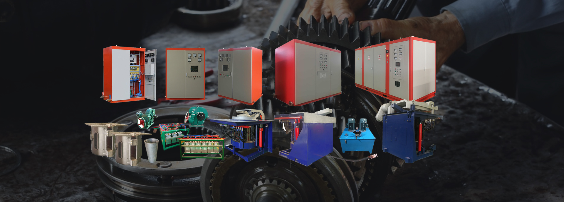
2 , machine tools without rotating ascending mechanism
This machine structure is shown in the figure above. The working principle is carried out by a crane when it does not include the hydraulic ascent and the worm gear rotating mechanism and the workpiece support, when the motor rotor is loaded and unloaded and the segment welding is rotated.